TL:DR The PCB was mislabeled.
Recently a particular set of smart plugs have been failing to operate with Home Assistant. I decided to flash them with Tasmota firmware to free myself from the cloud. There were a few challenges along the way, so here are a few breadcrumbs for those who choose the follow my path.
Disassembly
Shoving a putty knife into the seam worked reasonably well. I took notes from FixItFrank. I ended up with minimal damage to the case.
I was not able to remove the PCB from the case. Your mileage may vary, but I was able to work around this constraint.
Connections
I soldered some short wires to the required pins. I really tried to avoid this step, but I wasn’t able to hold all wires in place long enough to program the chip. I melted a big blob of solder onto the end of each of these wires, then held them in place while I heated them. The solder melted and slid down onto the PCB holding the wires well enough in place.
Programming requires 5 connections, 4 of which were labeled on the PCB. I’ve labeled them in the image above as well as the reset (RST) pin which was not labeled on my PCB.
I used an Arduino UNO to program the ESP8285 chip. In order to do this you’ll need to have an Arduino with a removable ATMega328 processor, and it needs to be removed. Presumably other 5V serial programmers would work as well. Tasmota has a few recommended choices.
Power Lines
I connected 5V and GND from the Arduino to the leads attached to the ESW01’s PCB with the matching labels. No rocket surgery here.
Data Lines
Every tutorial you will read will tell you to cross RX and TX meaning the RX from your serial programmer (Arduino in my case) should connect to the TX on the ESW01’s PCB and vice versa. Those people are right–except for today.
IMPORTANT: My ESW01’s PCB was labeled incorrectly. I had to connect RX to RX and TX to TX to successfully program the chip.
Reset Line
The Arduino has a reset pin. I didn’t use it and in hindsight, that may have been easier. Regardless, I connected a 5th wire to GND on the Arduino and manually touched it to the ESW01’s reset pad. More on that in the next section.
Programming
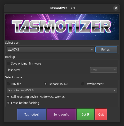
Tasmota has a list of flashing tools. I ran into some trouble with the web-based flasher that may have been a result of my own incompetence. I succeeded with Tasmotizer and the following incantation.
- Unplug the mains voltage. I really hope you knew that.
- Unplug the Arduino or serial programmer from the computer.
- Connect the 5V, GND, RX & TX wires as described above. IMPORTANT: the PCB is still mislabeled.
- Connect a wire from the programmer’s GND connection to the ESW01’s RST pad. This wasn’t labeled as RST on my ESW01, but I do have it labeled in the previous section. It’s the pad that sits between the button and the ESP8285 chip.
- Plug in the USB cable.
- The ESW01 powers on and the LED stays lit. This indicates you’ve put the chip into programming mode.
- In Tasmotizer, or your selected software, select the serial port, image and other options as seen below.
- Click Tasmotize!
That exact sequence yielded a successful program for all of my devices.
Configuration
A detailed walk-through of the configuration process can be found elsewhere, but in short…
- Use a Wi-Fi enabled device to connect to the Tasmota access point.
- Enter the Wi-Fi credentials for the network you’d like the switch to connect to
- Connect to the same Wi-Fi network you just provided
- Access the Tasmota device via it’s IP
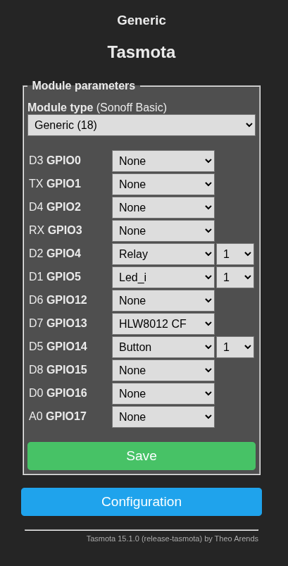
- Navigate to the Module section
- Module Type: Generic (18). Save & Reboot
- Set the following values
- D2 GPIO4: Relay 1
- D1 GPIO5: LED_i 1 (LED is on when switch is off)
- D7 GPIO13: HLW8012 CF
- D5 GPIO14 Button 1
- Save & Reboot.
- Enter MQTT and other settings to connect to Home Assistant.