Progress is coming slowly on the word clocks. I’ve assembled the LED driver boards. These boards host a series of standard serial-in parallel-out 595 shift registers that pump into ULN2003A NPN darlington transistor arrays. The schematic is pretty straightforward.

Simple Schematic
The arduino tells the shift registers which pins to turn on/off. When a pin goes high on the 595, the corresponding channel in the ULN2003A is connected to ground and the LED illuminates. I have to use the transistor for two reasons. First, the control/logic circuitry runs on 5V while the LEDs are running on 12V. Second, since there are multiple LEDs wired to each channel, if they were all wired to a single channel, the shift register would likely not be able to sink that much current and let the smoke out.
While the SN74HC595 shift registers I’m using have 8 outputs per chip, the transistor arrays only hold 7 transistors per chip. The word clocks have 21 switchable channels, so this worked out nicely. I simply left the first output on each of the 595 chips unconnected; it was in a bad location anyway. As they say in Hollywood, “We’ll fix it in post.” (Translation: we’ll fix it in software)

First LED Driver Board
Testing the LED driver board
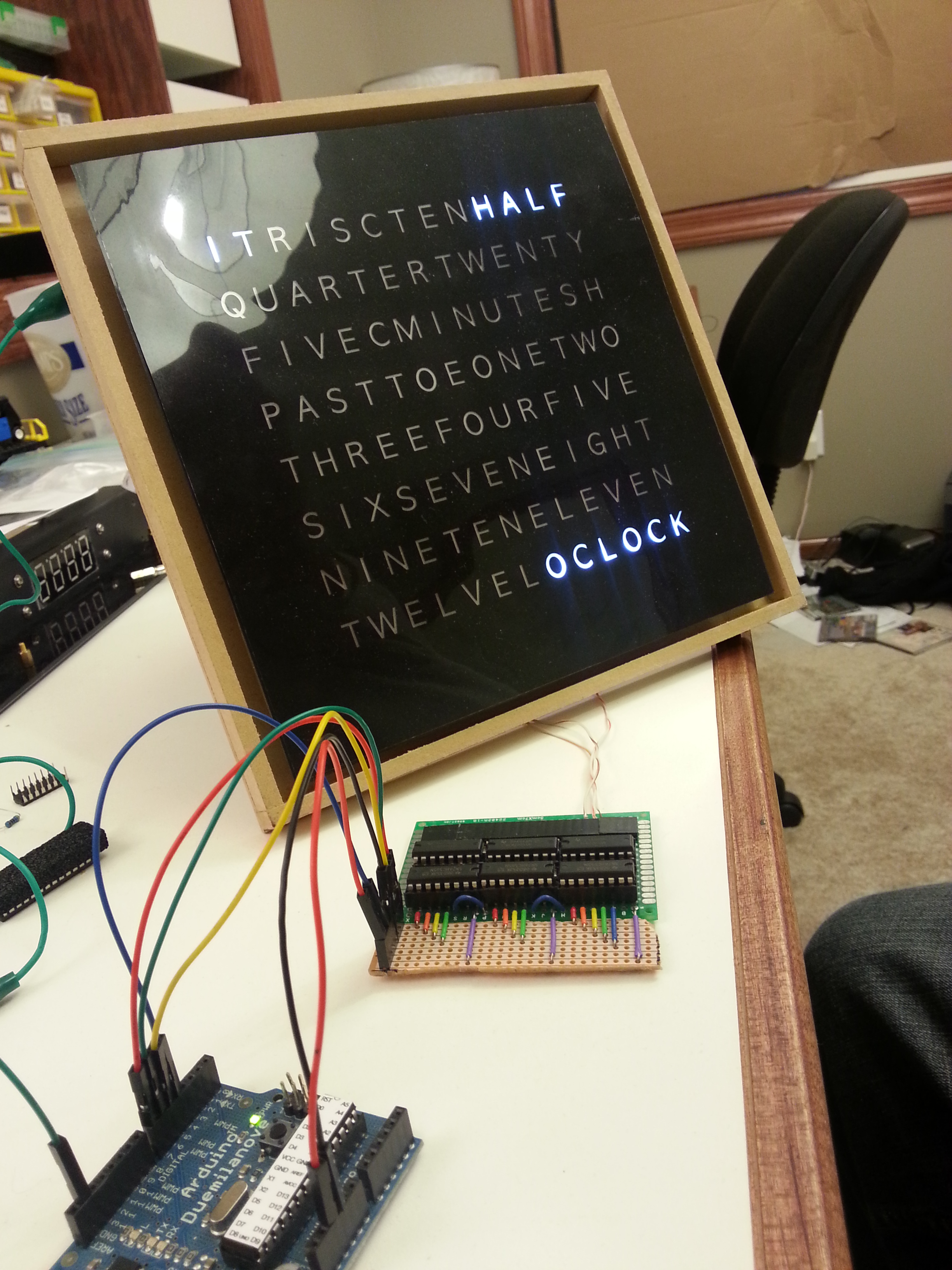
Pictured above is the first LED board. It is the simpler of the two as this clock will not have any RGB LEDs.
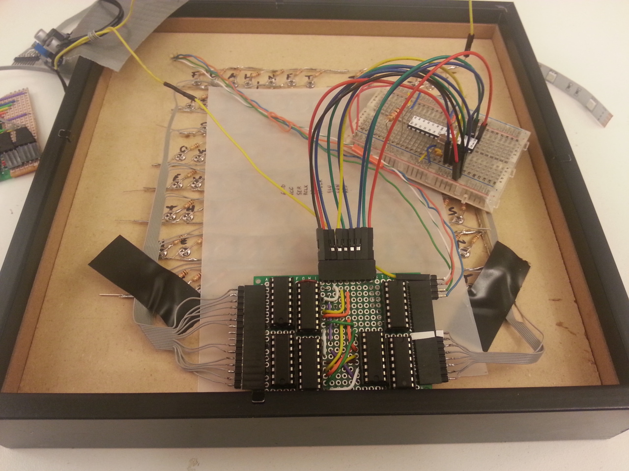
Second LED Driver Board
The second LED driver board required a 4th transistor array to switch the RGB LEDs. I’m running straight from the arduino’s PWM pins into the transistors. The are able to keep up with the Arduino’s PWM duty cycle. As a result of the extra IC, I had to rearrange the layout to fit everything all on the circuit board. The shift registers are in the center, while the transistors are on the outside. On the breadboard is an Arduino (or at least the important parts of one).
I didn’t snap any pictures, but the lights are all working on both clocks.
Still on the checklist:
- Hook up the RTC so that we know what time it is
- Move the Arduino off the breadboard and onto something more permanent.
- Write some code to make the magic happen.